# Silly FIRST Badge Part 2 - LED placement
One of the things I wanted to do for the FIRST badge was to model Team Ironic's logo, and have color controlable LED's in the space for the "electrons".
Because they were going to be separate (as opposed to being in a line as they have been on previous occasions when I've played with lighting), I decided to use the little PCB mounted WS2812B LED's from BTF-Lighting (opens new window). I quickly discovered that my soldering skills were very rusty, but managed to get a single working LED attached to the Raspberry PI so I could work out how the LED's and associated wiring would get inserted into the badge "frame".
Each LED comes mounted on a small PCB, and with a little measurement, I confirmed how large a space was needed. I wanted the PCB to fit "inside" a sort of collar, The collar would hold it in place, and my plan is to print (or otherwise create) a translucent curved white cover. This is because the LED's themselves are pretty bright and since the badge will be close to eye-level (especially at FIRST Lego League (opens new window) events), I definitely want to avoid any discomfort to others at those events.
For my previous 3D design work, I had been using the online Tinkercad (opens new window) tool, part of Autodesk's design toolkit. While that had worked well for me, it also had the challenge that it requires an active internet connection. Because this is something that would not typically be available to team members at FIRST competitions, I wanted to use a piece of software without that constraint. At the time, the team had not spotted that as FIRST sponsors Solidworks (opens new window), Autodesk (opens new window) and PTC (opens new window) all offered some form of free license to active teams. Because I wanted to use something that the kids would also be able to use, I plumped for the open source FreeCAD (opens new window). I would later come to regret that choice, but I'll tell you more about that in the next update.
While I had played with 3D modeling (specifically playing around with ray tracing many years ago), I hadn't needed to do anything with it for a long time, and even if I had wanted to, I really didn't have the time without people thinking I was seriously antisocial and/or getting complaints from neighbors about the inreasingly rundown appearance of our house. Because it wasn't completely new to me, I expected I'd find it reasonably easy. Nope. Try again! My first impression of the FreeCAD interface was very similar to my first impression of the Blender (opens new window) UI. A daunting number of tools and options with almost nothing operating in a way I found intuitive. Don't misunderstand me. I'm not saying that the UI for either those tools is a bad one, especially once you understand what everything is used for. However, at least for me, they did present an unexpected barrier to entry. I had a specific goal in mind and knew what I wanted to accomplish. I could probably have drawn a first angle projection on paper in an hour or less, but it took almost that long just to understand what the different modes were (and I'm still not sure I fully grok the part design vs part usage tools even now).
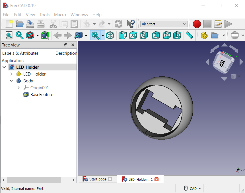
I eventually managed to persuade FreeCAD to produce what I was looking for. A simple half sphere from which a cylinder had been removed and a slit cut all the way through for the LED's wiring to pass through. Time to print it out and see if it worked. It didn't. I had suffered the first of many PEBKAC Failure's. While the LED and wires could (barely) pass through the slot, it was completely impossible for the LED to sit flat in the holder once the wires had been soldered on.
After a small adjustment, I ended up with this, which looks as if it might work as desired. I still haven't sorted out the cover portion yet, so there is a good chance that the holder portion will need modification later, but I'll worry about that when I'm closer to actually having something functional.
